
Our applied methods


We use a wide variety of procedures to carry out investigations with geophysical exploration methods.
Our surveys take place:
on land, on water (lakes, rivers, sea),
in drillings (downhole, crosshole, surface – borehole)
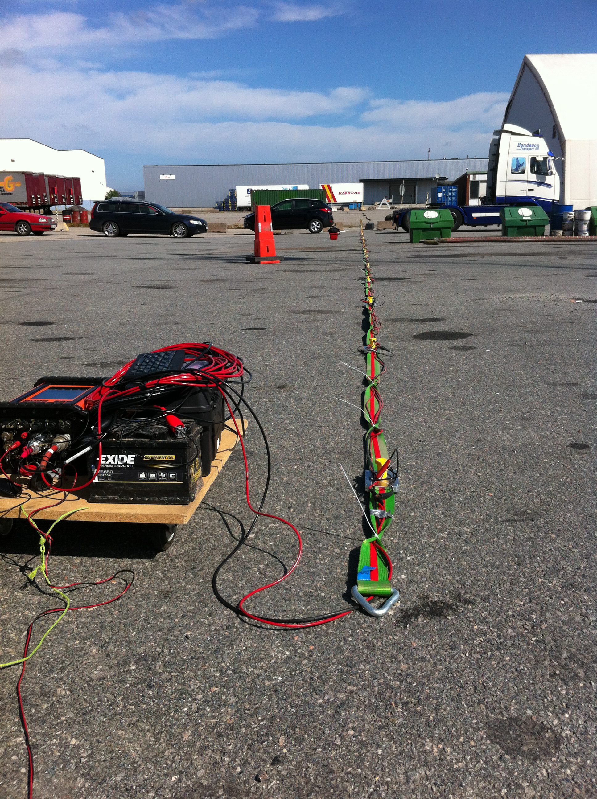
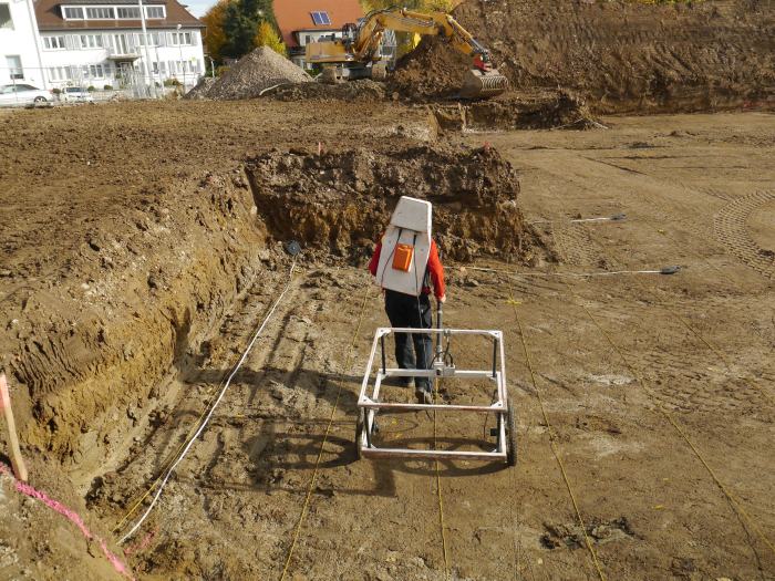
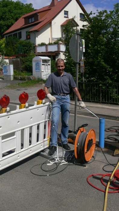
In DC geoelectrics, current electrodes placed on the surface of an area to be investigated are used to generate an electrical field in the ground. Resulting potential differences are recorded at various positions using so called potential electrodes. The measured values are affected by the geometry of the respective electrode arrangement and the electrical field and thus resistivity distribution in the subsoil.
Two physical processes or material properties in the soil influence the geoelectrical measurement: the electron conductivity of the rocks and the electrolytic conductivity of the substrate, which in turn depends on the water content present in the substrate and the ions dissolved in it. Both effects overlap in the measurement results and must be taken into account in the interpretation.
With modern measuring technology, so-called multi-electrode equipment, large underground areas can be scanned in 2 or 3 dimensions. Different measurement configurations with different advantages and disadvantages can be used. The selection of the appropriate measurement configuration(s) can therefore be of decisive importance for the result of a measurement campaign.
Common electrode configurations are among others: Schlumberger, Hummel, Wenner, pole-pole, dipole-dipole and pole-dipole. So-called mise-à-la-mass measurements are a special feature. Here, a conductive area of the subsurface is charged, i.e. used as an extended “current electrode”. This measuring arrangement is used, for example, in the exploration of groundwater flow paths.
The evaluation of the measured data usually takes place in two steps: First, a possible model of the spatial resistivity distribution of the ground is calculated using mathematical methods (1D, 2D or 3D inversion methods). In a second step, the spatial resistivity distribution of the subsurface is interpreted geologically. In addition to data quality and information content of the resistivity model, the geoscientific expertise and experience of the interpreters also play a decisive role concerning the outcome of a survey.
Geoelectric tomography is a measurement method that maps the spatial resistivity distribution of the substrate tomographically.
For special problems, self-potential measurements and measurements of the induced polarization (direct current in the time domain, alternating current in the frequency domain) can be carried out.
Areas of application:
- Geological stratum boundaries
- Groundwater table, underground waterways
- Fault zones
- Cavities
- Dolines, crevasses, covered boulders
- Buried objects, such as tanks, foundations
- Contaminated sites, landfill bodies
- Pipelines
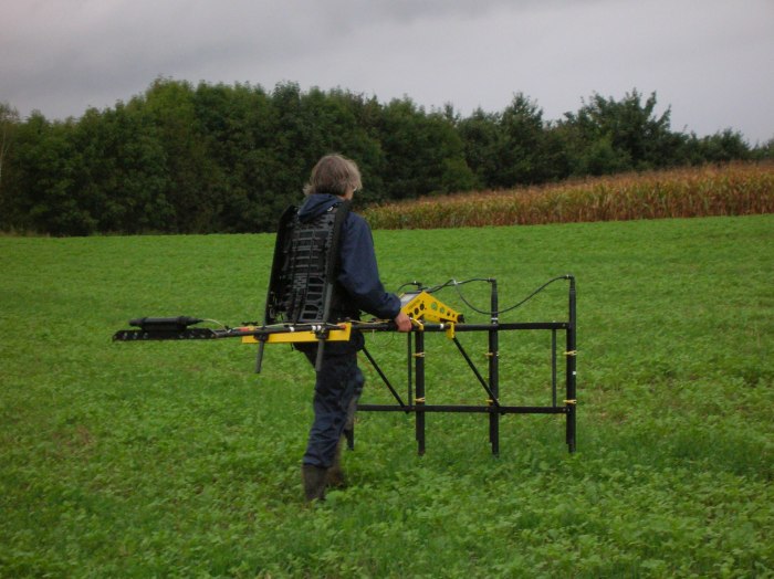
Electromagnetic methods are assigned to conventional geoelectrics and are used to investigate conductivity structures in the subsurface. Depending on the source of the exciting field, one speaks of active or passive methods, whereby the passive methods (VLF, VLF-R) use the fields generated by radio stations far away. In the active methods, transmitters are used to excite artificial electromagnetic fields. These transmitters operate in the frequency range between approx. 100 Hz and 60 kHz for engineering geological and geophysical questions.
The achievable exploration depths, resolutions and sensitivities of electromagnetic measuring systems strongly depend on the conductivity of the material investigated, the radiated frequency, the distance of the transmitting and receiving coils as well as the alignment of the coils (horizontally or vertically). Typical values for exploration depths range from 0.6 m to approx. 100 m. The results of electromagnetic mappings are presented in the form of isoline diagrams showing the distribution of electrical conductivity.
In addition to the mapping of geological formations, disturbances and fissures, special electromagnetic methods are used in line detection and in the location of metallic objects (Time domain electromagnetics, abr.: TDEM).
Areas of application:
- Geological stratum boundaries
- Groundwater table, underground waterways
- Fault zones
- Cavities
- Dolines, crevasses, covered boulders
- Buried objects, such as tanks, foundations
- Contaminated sites, landfill bodies
- Pipelines
Magnetic procedures are used to detect anomalies in the earth’s magnetic field caused by magnetization contrasts in the rocks or magnetized deposits in the ground.
The magnetization of rocks and ferromagnetic or ferrimagnetic objects is made up of an induced and a remanent part. The induced part depends on the prevailing external earth magnetic field (strength and direction). The remanent magnetization is permanent and independent of the current field. The superposition of both effects gives the measurable magnetization of a rock or object.
On the earth’s surface measurable effects caused by burried magnetic bodies not only depend on the magnetisation, shape and size of the bodies, but also in particular on their depth.
Areas of application:
- Object localization
- Archeology
- Detection of old deposits
- Delimitation of lithological units and investigation of fault zones in areas with differently magnetized rocks
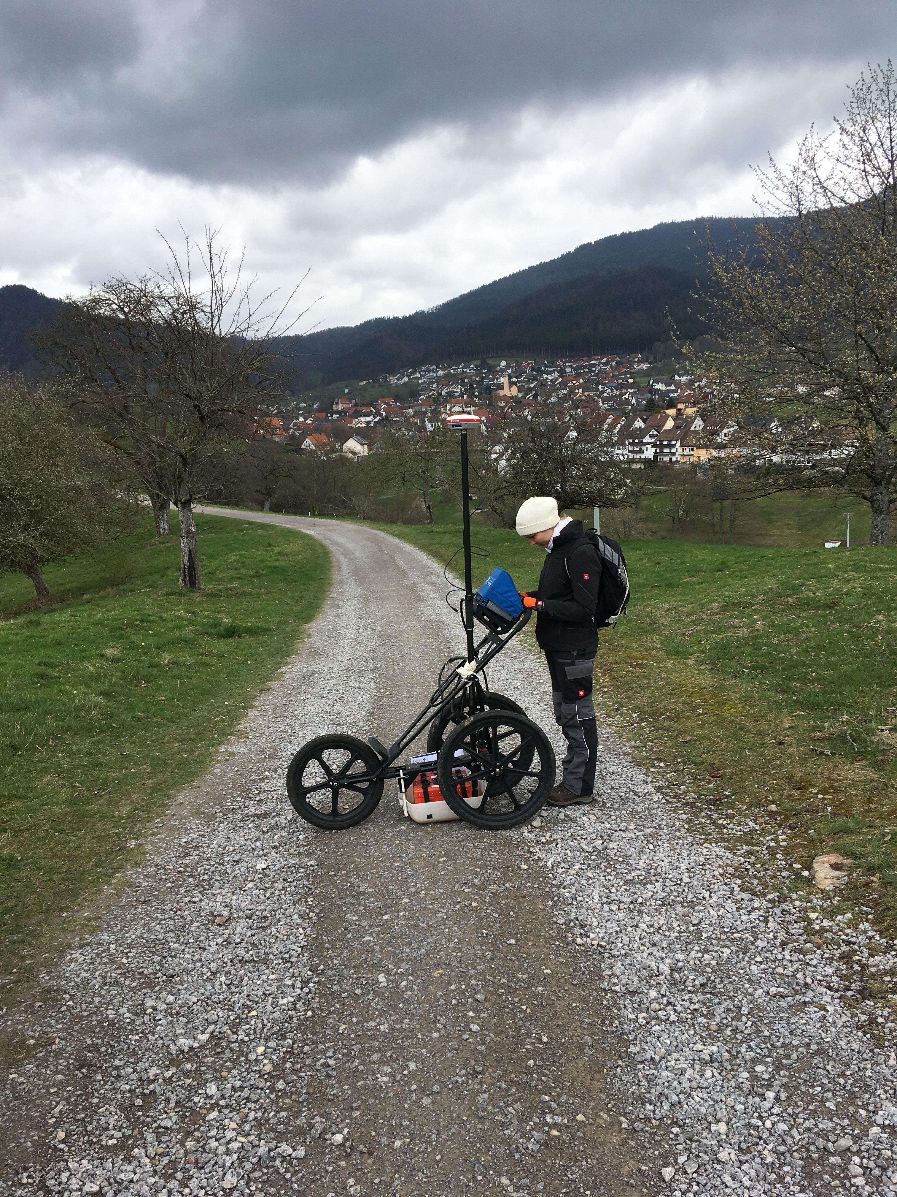
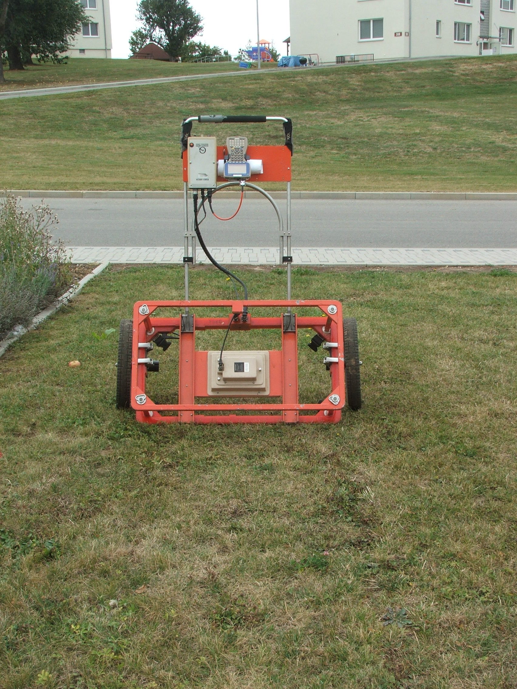
The ground penetration radar (GPR) or electromagnetic reflection method (EMR) is similar to that of an echo sounder in many respects: the propagation time and amplitude of reflected or scattered waves are recorded and displayed on a screen or printed on paper as a so-called radargram.
An GPR apparatus consists of a central transmitter and receiver unit and the antennas. During the measuring process, via antennas moved along the profiles to be examined, electromagnetic waves (high-frequency pulses) are transmitted into the material to be examined. Depending on the dielectric constants of the sample material and the objects or structures contained therein, the wave field is reflected or scattered.
The waves returning to the receiving antenna are preamplified, frequency-transformed and then transmitted to the receiver unit. Here a filtering as well as a further amplification of the received wave fields takes place. The amplitudes and propagation times of the signals are registered and stored within time windows whose lengths are to be selected depending on the problem to be solved.
The wave fields reflected by objects or structures are called anomalies if they are recorded in radargrams. The recording of anomalies requires that the electromagnetic impedance contrast of searched structures or objects is large enough for detection.
Areas of application:
- Object localisation
- Cavity detection
- Investigation of fault zones, layer boundaries, anomalies, etc.
- Survey of the groundwater surface
- Landfill exploration
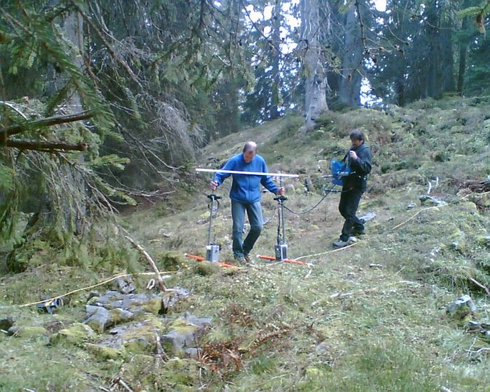
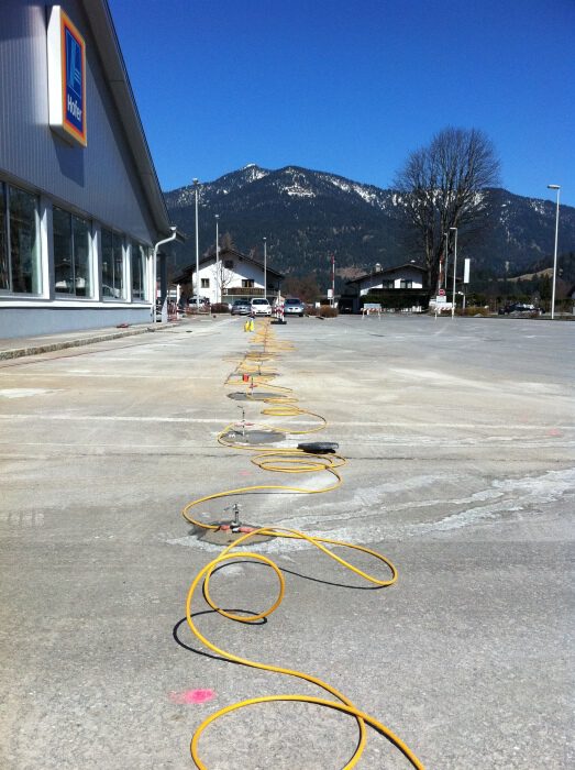
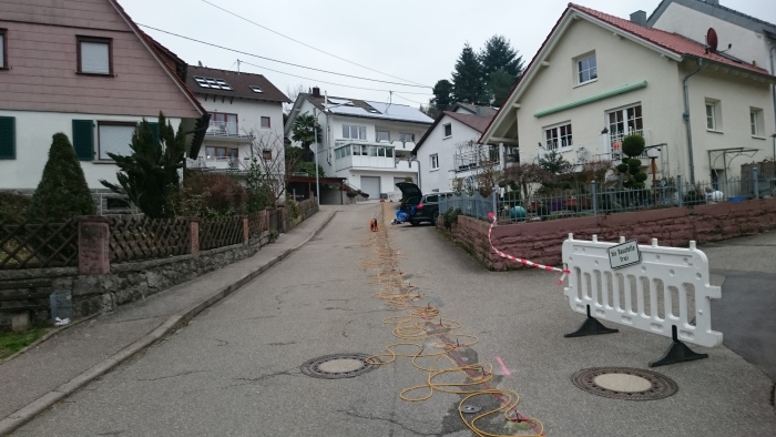
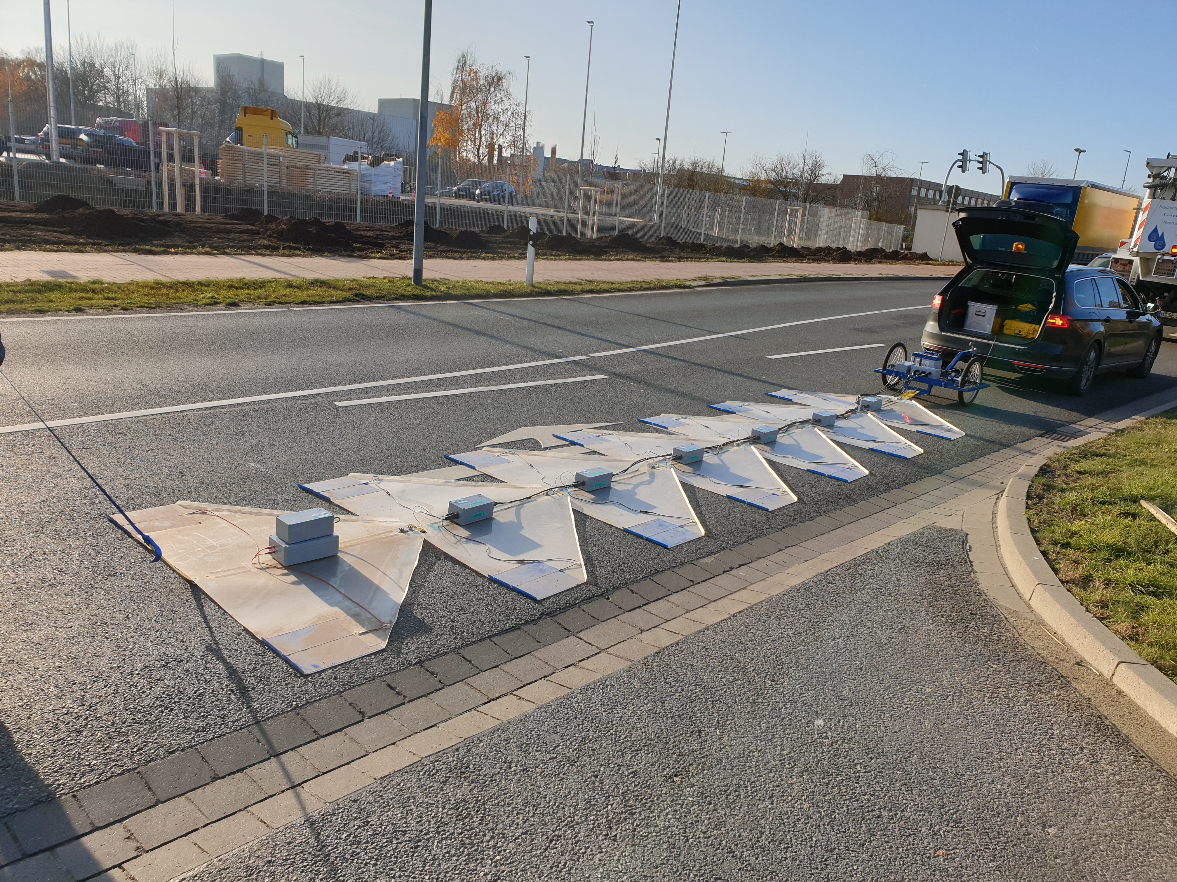
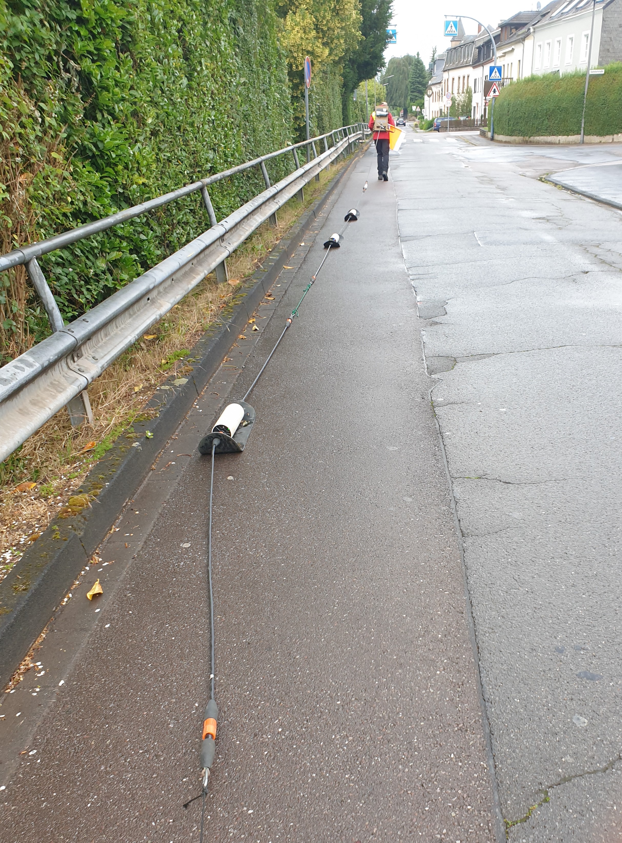
Seismic methods use artificially excited elastic waves and wave fields as information carriers, which are processed to images of the subsoil. Reflection, refraction, diffraction, absorption and scattering influence the propagation of seismic waves. The crucial parameter for wave propagation in the ground is the material-dependent wave velocity, which is determined by soil density, elastic modulus, porosity and the like. From the transmitter-receiver geometry and the measured propagation time of the seismic waves, wave propagation velocities in individual layers can be determined.
With a seismic source (hammer, drop weight or explosive) waves are generated in the ground, which propagate as so-called body waves or surface waves. Body waves can return to the surface through reflections as well as refractions and can be observed there. A distinction is made accordingly between reflection seismics and refraction seismics.
Surface waves propagate along the surface, with the direction of vibration in both horizontal and vertical planes perpendicular to the direction of propagation. Penetration depth is frequency dependent. In seismic surveys with surface waves we use the MASW (Multichannel Analysis of Surface Waves) method.
Areas of application:
- Soil investigations and exploration of soil structures
- Mapping of loosening zones (tunnelling, landfill sites)
- Mapping of the permeability of rubble
- Mapping of unconsolidated rock layers
- Localization of fracture zones (=> underground waterways, problematic areas in underground mining)
- Mapping of geological and anthropogenic layer boundaries (e.g. bedrock surface)
Sub-bottom profiling is an investigation method for structures in the subsoil of water covered areas, i.e. in the subsoil of rivers, lakes and seas. The exploration method in principle corresponds to that of an echo sounder. A sound signal is emitted into the ground where it is reflected and refracted. The reflected signals are recorded up by one or more receivers attached to a ship.
Penetration depth of the signal used among others depends on frequency. High frequencies penetrate less deeply into the ground, but deliver a higher resolution of the structures. At low frequencies it is the other way around. Depending on the structures to be examined and the level of water cover, different frequencies are used.
The data analysis is computer-aided and provides high-resolution images of the subsoil to be examined.
Areas of application:
- Exploration of the geological ground under the seabed
- Offshore deposit exploration (oil, gas, etc.)
- Offshore pipe location
- Underwater exploration of bridge foundations
- Investigation of the subsoil of harbour basins, rivers, etc.
The choice of a geophysical method (or several methods) suitable for solving a specific problem, depends on many important details and requires a high degree of technical knowledge and experience: The given geological situation and the expected parameter contrasts in the measuring range must be assessed in order to determine relevant measurement parameters.
A multitude of other boundary conditions also play a role, e.g. the necessary exploration depth and thus often the spacial boundary conditions, disturbing influences in the vicinity of the measuring range, meteorological and temporal factors and last but not least the economic possibilities for the project.
In addition, a large number of measuring devices are available for the different measuring methods, each developed for different applications. Here, too, it is important to make a selection.
Under the keywords listed above you will find brief descriptions of the most common geophysical methods we use.
We will be happy to advise you on your specific questions. Please do not hesitate to contact us.